A multimeter is a very useful device with several applications such as measuring current, voltage, resistance, capacitance, and other checks such as the continuity of a circuit as well as the temperature of electric circuits. All these measurements play a vital role and are used for a wide range of applications, like finding out possible faults in a capacitor. We can use a multimeter can be used in several ways to check the condition of a capacitor, which ultimately helps us to eliminate the cause of error in an electronic board. See below for a complete guide on how to test a capacitor with a digital multimeter.
Capacitance Test:
Before going into further details it is important to know that, what is a capacitor? The capacitor is an energy storage device and a faulty capacitor can lead to faults in circuit boards as well as machines equipped with a start capacitor. We will discuss briefly the steps involved in testing a capacitor
- As we know capacitor stores electric charge between two closely packed plates and these are isolated. Even when the power is removed from a circuit a capacitor can be still charged and we can get an electric shock so the first step involved in the capacitor testing with a multimeter after removing it from a circuit board is the discharging of a capacitor. To discharge a capacitor we connect the terminals of a capacitor with it with a resistor of relatively high-value resistance e.g. 20 k Ω, 5W resistor for a few seconds as shown in the picture below
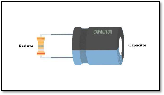
Figure 1 Discharging of Capacitor with high ohm resistance - In the second step, we set the capacitor on the capacitance mode, If the capacitance isn’t equipped in all digital multimetersmake sure you are using the multimeter that has secondary options like capacitance we will switch our multimeter’ selector to the capacitance symbol. If your device has more than one capacitor value select the correct range which is relatively higher than the rated value of your capacitor.
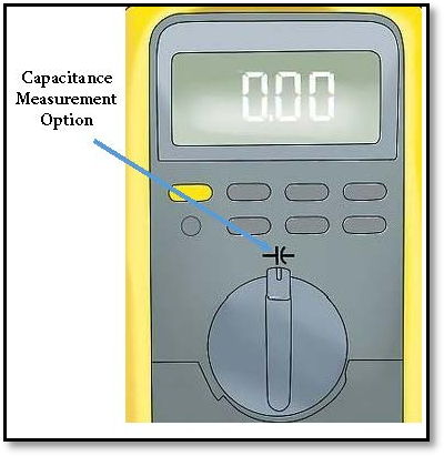
Figure 2 Correct position for selector to measure capacitance
- In the next step, we will connect the probes of the multimeter with the capacitor terminals. There is point a point to remember that container-like capacitors (electrolytic capacitors) are polarized so it's important to identify the positive and negative terminals of the capacitor and also connect the probes with the capacitor accordingly as shown in the figure below. The multimeter will send a current to charge the capacitor and it measures the voltage across its terminals that will take a few seconds to complete and the screen will show the capacitance value. Note that every capacitor has its tolerance value which is usually expressed in percentage. This value indicates the range of deviance of capacitance value for a given value of capacitance. For example, a 2000μF capacitor with 10% tolerance indicates that the capacitance value is between 1800μF to 2200μF.
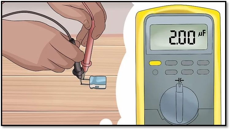
Figure 3 Connecting probes with terminals of capacitor
Voltage Test:
A voltage test has been done on the capacitor to determine the charge storage capacity of the capacitor. Through a voltage test of the capacitor, we can determine, whether the capacitor has an accurate amount of charging while using it in our circuit. So a malfunction of the circuit could be due to the disability of a capacitor for not storing charge properly
- The first step involved in the voltage test after discharging the capacitor is to connect it to a battery with jumper cables, we must be careful in case of polarities especially when we are dealing with polarized capacitors .
- Connect the capacitor with the power source accurately with appropriate capacitor pins and make sure the current is flowing properly through the circuit. By doing this if a capacitor is working fine it will hold the same value of volts supplied to the capacitor through the power source. For example, if we are using a 12 V battery the holding voltage by capacitor will be 12V as well. After connecting the probes the multimeter will show the same voltage as of power source that will rapidly discharge to 0V. If the multimeter screen is not showing any value it means the capacitor is not holding any charge and it’s a faulty capacitor.

Figure 4 Capacitor's Voltage Test with multimeter
Resistance Test:
The resistance test of the capacitor has the same initial steps involved in the capacitance
- After discharging the capacitor we move the selector of the multimeter on the resistance option as shown in the pic below
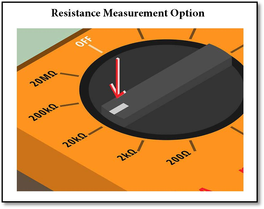
Figure 5 Resistance test of capacitor
- Connect the probes of the digital multimeter with the positive and negative terminals of the capacitor. The multimeter will send a current to charge the capacitor if the output value has increased from a very low value to a negligible value the capacitor is charged and working properly.
- The constant low value of resistance indicates that the capacitor is short-circuited and the high constant value shows that the capacitor is open and need to be changed in both cases of open and short circuit.
Continuity Test:
We can check the good or faulty condition of a capacitor through a continuity test. For this purpose connect the probes of the multimeter with the terminals of the capacitor. Switch the selector of the multimeter to continuity mode. If the capacitor is in good condition we will hear a beep sound or in some models of multimeter blinking of LED light equipped on multimeter will occur. If no sound or LED blinking occurs it indicates that our capacitor is faulty.

Figure 6 Continuity test of capacitor with multimeter