Introduction
Definition of a Capacitor
A Capacitor is an electronic component that stores charge and electrical energy and is able to release the stored charge in a circuit. It is also often referred to as a capacitor or capacitor. The main function of a capacitor is to store and release electrical charge, which makes it versatile in electronic circuits.
Capacitors are usually made of an insulating material (called a dielectric) sandwiched between two conductive plates (usually metal). The dielectric between the conductive plates can be air, ceramics, polyester film, aluminum electrolyte, etc. One of the conductive plates is connected to the positive electrode of the circuit, and the other is connected to the negative electrode of the circuit. When a voltage is applied to the capacitor, a positive charge accumulates on the positive plate and a negative charge accumulates on the negative plate. This charge is distributed in the dielectric, resulting in the formation of an electric field.
Explanation of a Capacitor Symbol
The capacitor symbol in a circuit diagram represents the physical capacitor element. It's typically drawn as two parallel lines or plates, indicating the two conductive plates in a physical capacitor. These plates are separated by a non-conductive substance or insulator, known as a dielectric.
In circuit diagrams, the parallel lines can be drawn either vertically or horizontally. For polarized capacitors (like electrolytic capacitors), one of the lines may be curved or the plus " " symbol is used on the positive side.
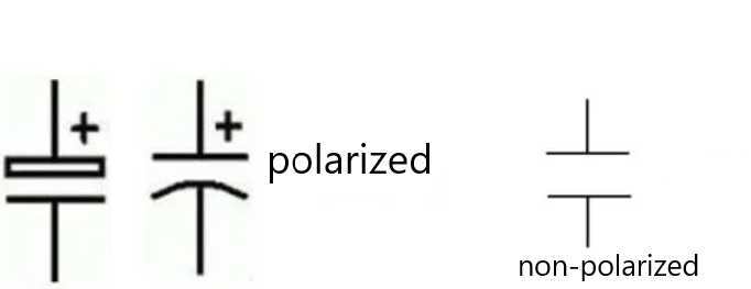
Figure 1: The symbol representation of a capacitor in a circuit diagram
The symbol doesn't depict the actual physical layout of the component, but it helps to understand its function - storing and releasing electrical charge - and how it's connected in the circuit. When you see this symbol in a circuit diagram, it indicates that a capacitor is included in the circuit at that point.
Types of Capacitor Symbols
Polarized Capacitor Symbols
The two pins of a Polarized Capacitor have a clear positive and negative polarity, and the polarity of the two pins cannot be reversed when in use. Most common Polarized Capacitors are electrolytic capacitors, which can be divided into aluminum electrolytic capacitors and tantalum electrolytic capacitors according to different materials.
Polarized Capacitors can filter out clutter or interference waves in the circuit, so they are also called smooth filter capacitors. The physical shape and circuit graphic symbols of polarized capacitors are shown in the figure.
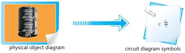
Figure 2: Polarized capacitor and its circuit graphic symbols
Non-polarizedized Capacitor Symbols
The two pins of the non-polarizedizedr capacitor have no positive or negative polarity, and the two pins can be exchanged and connected when in use.
The physical shape and circuit graphic symbols of non-polarizedized capacitors are shown in the figure.
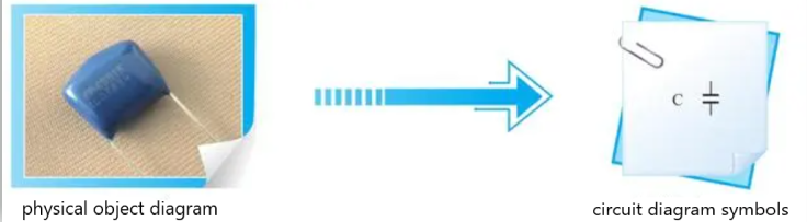
Figure 3: Non-polarized capacitor and its circuit graphic symbols
In the production of non-polarized capacitors, due to the characteristics of the material and production process, its capacitance has been fixed, so it is also called a fixed capacitor. The non- polarized capacitor mainly plays the functions of coupling, smoothing and filtering, phase shifting and resonance in the circuit.
There are various types of non-polarized capacitors, such as colored ring capacitors, paper capacitors, porcelain dielectric containers, mica capacitors, polyester capacitors, glass glaze capacitors and polystyrene capacitors. The circuit graphic symbols of these capacitors in the circuit are the same, the physical shape is different, and they have different characteristics.
Variable Capacitor Symbol
A variable capacitor is one where the capacitance value can be manually adjusted. This is often used in tuning circuits, such as those in radios. The symbol for a variable capacitor is similar to the fixed capacitor symbol but has an arrow through one of the plates to indicate that it's adjustable. The symbol can be represented like this:
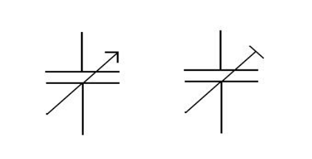
Figure 4: Graphic symbol for variable capacitors
Capacitor Symbols on a Multimeter
Explanation of How a Multimeter Measures Capacitance
A multimeter measures capacitance by charging a capacitor with a known current, measuring the resulting voltage, then calculating the capacitance using the formula C=Q/V, where Q is the charge stored in the capacitor and V is the voltage across the capacitor. This is done automatically within the multimeter.
Understanding the Capacitor Symbol on a Multimeter
The capacitor symbol on a multimeter is usually represented by a capital letter "F," which stands for Farads, the unit of capacitance. Some multimeters may use a symbol similar to that used in circuit diagrams (two parallel lines), but this is less common.
When you want to measure the capacitance, you switch the multimeter dial to the setting with the capacitor symbol. You then connect the probes to the capacitor you're measuring, making sure to observe proper polarity if the capacitor is polarized. The multimeter display will then show the capacitance of the capacitor in Farads (or often in microfarads, µF).
Variations in Capacitor Symbols
Differences in American and European Symbols
In circuit diagrams, capacitor symbols can vary slightly between American and European standards.
- American: In American notation, a fixed (non- polarizedized) capacitor is typically represented by two parallel lines. A polarized capacitor, like an electrolytic capacitor, is often represented by a plus " " symbol on the positive side, or a curved line representing the negative plate and a straight line representing the positive plate.
- European: In European notation, a fixed (non- polarizedized) capacitor is usually represented by a straight line and a curved line parallel to each other, while a polarized capacitor maintains the same representation as in American notation.
Other International Variations
In other parts of the world, the capacitor symbols used may follow either American or European conventions, or sometimes a mix of both. It's also not uncommon to see the symbol of a variable capacitor (an arrow through one of the plates) used to represent a generic capacitor in some regions. Always refer to the legend or key provided with the circuit diagram to understand the symbols used.