The USB type-C port provides power delivery to operate the system, charge batteries or source power to connected peripherals.
The USB Type-C connector was first introduced over five years ago, and in that time, it has been widely adopted as the connector of choice for portable consumer electronic products. This single connector provides cellphone handsets, tablets, and other portable devices with an interface for data, video, and audio. The USB Type-C port also provides power delivery to operate the system, charge batteries, or source power to connected peripherals. The connector receptacle has a reversible pin configuration to eliminate the concern for connector polarity. However, external ports on portable products expose the device to several dangers, short-circuits to ground or adjacent connector pins, possible application of voltage or signal levels outside of designed limits, and electrostatic discharge (ESD) events. The very tight pin pitch or spacing of contacts within the USB Type-C connector poses risks and challenges. The pins within the connector have 0.5-mm spacing, making them vulnerable. Short-circuits between pins could occur if a plug gets twisted upon insertion to the receptacle or in the event of a metallic foreign object contacting the pins. Another design concern for any portable product with a USB port is that there is no way to control what third-party peripheral an end user may connect to the port. Such devices may not be compliant with USB or product specifications, causing damage to upstream circuits connected to the port. Previously, port protection devices employed discrete devices or single-purpose protection switch ICs to safeguard VBUS and data lines. These solutions are costly and require valuable printed-circuit–board space inside a product. Discrete protection solutions are also resource-intensive for the system controller hardware and for validation to design standards. To alleviate this issue, highly integrated port protection devices are now available to simplify ease of use, the design task, and validation to industry standards. An example is the new KTU1125 from Kinetic Technologies, Inc. A device like the KTU1125 can add needed circuit protection, reduce component footprint size, and ultimately reduce product cost while increasing product reliability.

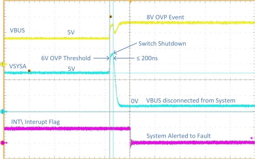
A primary function of the USB Type-C connector is to connect the device VBUS to an external power source to power the system and charge internal batteries. In many cases, VBUS serves a dual role to source power to connected peripheral devices. The VBUS pin can have an applied input voltage level between 5 V and 20 V, with current levels ranging from 500 mA to 5 A, attaining power levels up to 100 W. Per the USB standard, the initial voltage applied to VBUS should not exceed 5 V. The KTU1125 and devices like it have default overvoltage protection (OVP) at 6 V to guard against faulty voltage sources. For advanced designs, the OVP shutdown threshold can be increased dynamically by I2C bus programming control to accommodate higher input port power functions. This allows the device to be safeguarded at startup, yet can also adjust to any given OVP level to support device operation withstanding the specified limits of the USB standards. When an OVP event occurs, a typical protection switch will shut down and disconnect VBUS from the system in less than 100 ns to prevent damage from occurring. Another parameter of concern for a VBUS protection switch is the maximum surge or standoff voltage specification. The switch will shut down to protect the system when the applied input exceeds the OVP threshold. The switch must be capable of withstanding voltage levels far higher without damage to protect itself as well as the system. This parameter is defined as the surge-voltage specification. A good protection switch like the KTU1125 can survive as much as 100 V applied from VBUS to ground without damage. Under normal operating conditions, the VBUS protection switch monitors current flow regardless of current-flow direction. If current flow exceeds a preset level, the overcurrent protection (OCP) will be triggered. In the event of a short to ground, the OCP circuit will disconnect the switch and resume operating when the short is removed. The KTU1125 also provides the designer advanced programmable overcurrent-limit features to limit current to a preset level to allow system operation under guarded conditions. In an off state, the VBUS protection switches employ reverse-current blocking to prevent an externally connected device from damaging the system or draining the internal battery.
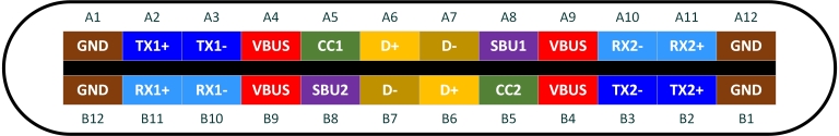
The USB Type-C standard provides slow-speed data and control input/out lines that are located adjacent to the VBUS pin. The layout of the USB Type-C connector has the advantage of mirrored pins that allow connection regardless of plug orientation. However, this feature means pins must be safeguarded against external adverse conditions as well as the possibility of direct shorts to VBUS. Referring to Figure 3, one can see the risk of short-circuits between the configuration control (CC) and sideband use (SBU) pins adjacent to VBUS due to the fine 0.5-mm connector pitch. Twisted plug insertions to the USB Type-C receptacle or metallic foreign objects can create shorts to VBUS.
Applied voltage levels to VBUS can be as high as 20 V under normal conditions, which can easily damage upstream CC and SBU data line circuits. However, the CC and SBU pins are used for different functions and have different protection requirements.
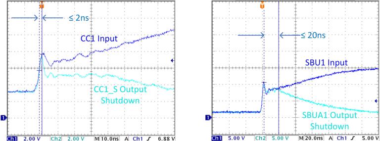
The CC pins are used for functions as their name implies — control and configuration of the port function, which may include cable detection, plug orientation, role detection, or mode. In some uses, the CC1 pin can be switched to source power for the VCONN function. Typical signal levels applied to the CC pins can range up to 5 V; thus, the OVP threshold for these pins are typically set to 6 V. Therefore, the port should shut down and be protected if shorted to VBUS with a level greater than 5 V or when the applied signal level exceeds the nominal 5 V maximum. The CC pins should also withstand surge-voltage levels after shutdown up to 25 V without damage to be compliant with port standards (IEC16000-4-5). Figure 4 shows a 20-V hot-plug shutdown-protection event. The input side to the CC or SBU switches rises to 20 V, while the switches disconnect to output side to protect the system. Under the role where the one CC pin is assigned the VCONN function by the system, it is designed to source up to 1.0 W at 5 V. To protect the upstream battery or power source, a current-limit control is needed. The KTU1125 provides this feature with user-selectable VCONN current-limit options.
Systems commonly task the Power Distribution (PD) controller to monitor the CC lines to capture a voltage-drop event for the purpose of role swapping from sinking current on VBUS to sourcing current. The USB-PD standard specifies the time to switch from current-sinking to sourcing to 150 μs. This is the time in which the PD controller detects a role swap, relays the information to the system, and has the system react to avoid power failure on VBUS. This can be a problem when the device connected to the port is in the middle of transferring volatile data and risks the chance of data loss. To relieve the dependance on a PD controller and uncertainty of system-response time to meet the 150-μs requirement, the KTU1125 has the unique feature to self-monitor the CC lines for fast role swap (FRS) conditions. When the FRS function is enabled via the I2C interface, the KTU1125 will monitor the CC1/CC2 lines for a condition where VCCn ≤ 0.49 V for 30 μs ≤ time ≤ 50 μs. When a CC line condition is met for FRS, the KTU1125 will switch VBUS from current sink to current source in 150 μs to reduce the chance of power disruption on the VBUS. In addition, the IC provides a hardware FRS flag to alert the system for the requested function change.
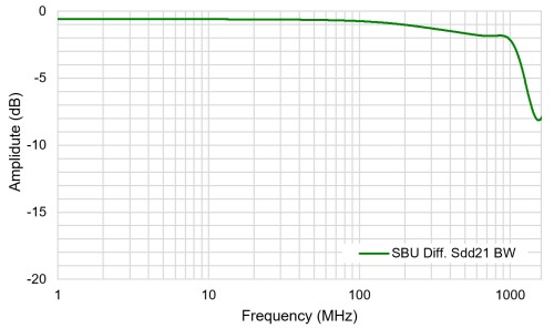
SBU inputs are typically employed for alternate mode functions or DisplayPort high-resolution video features. The multi-use nature of the SBU pins requires a 2:1 MUX from the port to the system to accommodate different DisplayPort and alternate mode functions to the upstream system. Due to the high-speed data requirement for the SBU protection switches and MUX, they need low-capacitance properties to achieve high-signal–bandwidth capabilities typically in the range of 1 GHz. Figure 5 shows the SBU analog switch differential bandwidth is greater than 1 GHz to maintain high-speed data integrity. For designers of protection ICs like the KTU1125, this poses critical design tradeoffs because switch properties that create high voltage and electrostatic discharge immunity are capacitive and bandwidth-limiting to an analog switch. The KTU1125 design and technology have been balanced to achieve both goals of high bandwidth for signal integrity while providing required high-voltage protection. SBU pins have the same risk exposure to VBUS and external overvoltage events as the CC pins but require a lower OVP threshold, as the nominal expected signal level should not exceed 3.6 V. To satisfy this requirement, the KTU1125 provides a typical OVP shutdown threshold of 3.83 V to safeguard the upstream system. Shutdown standoff voltage protection on these pins is rated up to 24 V, so no damage will occur if shorted to VBUS at 20 V.
No matter how careful a product is designed or how the product may be used, all pins of a USB Type-C port can be exposed to ESD events. There is no way to eliminate the chance of ESD events to a port on a portable product, so any port protection switch must safeguard against ESD events to protect itself and the system. As a given minimum, all switch IC pins should withstand IEC61000-4-2 contact discharge levels up to ±8 kV and air-gap discharge levels to ±15 kV. Under OVP shutdown or when the device is disabled, surge voltage levels should follow the IEC61000-4-5 standard to ±100 V for the VBUS switch and 25 V to the CC switches. ESD protection specifications are important limits that shouldn’t be overlooked for product reliability.
To round out the versatility of a protection switch for a USB Type-C port application, default functions and programmability should be considered. The KTU1125 in its default configuration can be employed for full protection of the VBUS, CC, and SBU data lines without the need for setup control by the PD controller, which can simplify low-cost designs. At the same time, a device like the KTU1125 can provide full system control and flexibility via the integrated I2C interface and requires I2C control before current is permitted to flow on the VBUS. Switch status, OVP thresholds, current-limit levels, and fault status can all be interrogated and set by the system dynamically as conditions or modes change with peripherals connected to the port.
For manufacturers of portable electronic products, end-user perception of product brand and quantity are directly affected by the reliability of the devices they purchase. Product manufacturers have no control over what might be connected to USB ports on their devices. Third-party and non-compliant external power sources and peripherals may be used with their product, which is a risk that can be mitigated only by making the product as robust as possible. The quest for designers of portable products to balance functionality and data port speed versus product quality and reliability will always be a continued challenge. Thankfully, IC manufacturers are stepping up to help alleviate this complex task. Devices like the KTU1125 and others like it provide robust protection from overvoltage, ESD, and overcurrent events. They also add functionality and compliance with USB Type-C port standards while resolving power control and high-speed data requirements.