CONTENTS:
How does L298N motor driver work?
L298N specifications & features
What is L298N Motor Driver
The L298N is a dual H-bridge motor driver chip designed to control DC motors or stepper motors. This chip can simultaneously control two DC gear motors, allowing for different actions, with a voltage range of 6V to 46V and a maximum output current of 2A. Additionally, it features overheat protection and feedback detection capabilities, enabling direct control of the motors. By setting the control levels through the I/O inputs of a microcontroller, users can easily achieve forward and reverse operation of the motors. Its simple operation and high stability make it suitable for driving high-current applications in DC motors.
The L298N motor driver module is a commonly used motor driver that primarily consists of the L298N integrated circuit, heat sink, connectors, and terminals. This module employs a dual H-bridge design that facilitates both forward and reverse control of the motors, as well as PWM speed control. It offers high efficiency and low heat loss advantages. When using the L298N module, it is essential to adjust according to the rated voltage and current of the motor to ensure circuit stability and reliability. A mode is shown below:
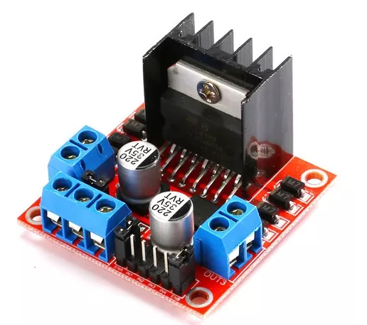
Figure 1: L298N motor driver model
L298N motor driver circuit
The L298N motor driver module is a module used to control DC motors, and its driving circuit is a commonly used dual H-bridge driver circuit. It typically includes the L298 motor driver IC, DC motors, power supply, connecting wires, and more. In this circuit, IN1, IN2, IN3, and IN4 are the logic control pins on the L298N driver, with each motor having two corresponding pins. The following is the circuit diagram for the L298N motor driver.

Figure 2: L298N motor driver circuit diagram
L298N motor driver pinout
The L298N has a total of 15 pins, including power pins, logic control pins, output pins, and enable pins. The following diagram shows the pinout for a common L298N motor driver board.
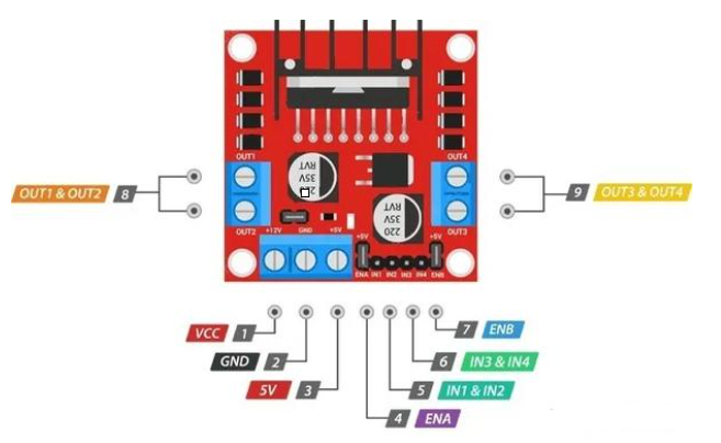
Figure 3: L298N pinout
Pin Configuration
|
|
Power Supply Pin |
|
Logic Control Pins |
|
Output Pins |
|
Enable Pins |
|
VCC |
External power positive, supplies power to the driver board, voltage range 5-35V |
IN1&IN2 |
Input pins of motor driver A, controls the rotation and angle of motor A. |
OUT1&OUT2 |
Output pins of motor driver A, connects power to the motor being driven. |
ENA |
By inputting a PWM signal to this pin, the speed of motor A can be controlled. |
|
GND |
External power negative, completes the circuit loop |
IN3&IN4 |
Input pins of motor driver B, controls the rotation and angle of motor B. |
OUT3&OUT4 |
Output pins of motor driver B, connects power to the motor being driven. |
ENB |
By inputting a PWM signal to this pin, the speed of motor B can be controlled. |
|
5V |
Internal logic power supply pin for the driver chip; if a 5V jumper cap is installed, this pin can output 5V to external devices. |
|
|
|
|
|
|
Understanding the pinout and circuit diagram of the L298N is crucial for correctly connecting and using this chip. As shown in the diagram, the L298N driver features ENA and ENB pins, which connect to the PWM pins of an external microcontroller (such as Arduino). By using PWM signals from the microcontroller, you can modulate the ENA and ENB pins of the L298N, thereby controlling the average voltage output to the motors and adjusting their speed. Additionally, by manipulating the levels of the IN1, IN2, IN3, and IN4 pins, you can control the rotation direction of the motors.
How does L298N motor driver work?
L298N utilizes the principle of H-bridge circuits to control the flow of current, thereby enabling precise regulation of motor speed and direction. The H-bridge consists of four switches (transistors or MOSFETs) arranged in a specific bridge-like configuration, which effectively controls the direction of current flow and the rotation of the motor.
In the L298N, the H-bridge circuit is divided into two sections, each responsible for controlling one motor port. Each section comprises an upper half-H-bridge and a lower half-H-bridge. When both switches in the upper half-H-bridge are closed, current begins to flow between the two ports connected to the motor, causing it to rotate clockwise. Conversely, when both switches in the lower half-H-bridge are closed, the direction of current reverses, resulting in counterclockwise rotation of the motor.
By managing the states of these switches, the L298N achieves accurate control over both the speed and direction of the motor.
ALSO READ: What is an H-bridge:circuit, construction & working
L298N specifications & features
- Logic Supply Voltage: 6-7V
- Driver Supply Voltage (VS): 4.8-46V
- Logic Operating Current (Lss): ≤36mA
- Maximum Power Dissipation: 25W (at T=75°C)
- Operating Temperature: -25°C to 130°C
- Driving Method: Dual-channel high-power H-bridge driving
L298N functions
- Convert the control signals output from a microcontroller or other signal sources into the voltage and current signals required by the DC motor.
- Process the input signals to achieve functions such as forward and reverse control of the DC motor, PWM speed regulation, and overload protection, ensuring the stability and reliability of the motor.
- Dual H-bridge drivers typically feature current protection capabilities, allowing them to monitor the motor's current and take protective actions when it exceeds a set threshold, preventing overload and damage.
L298N motor driver datasheet