Most places around cities, towns, highways and even estates are lit during dark hours or at night in most regions of the country. Manual control of these lights can prove to be difficult and at times inconvenient. One of the solutions that are most commonly used is timers, however, this approach can be quite limited in some time zones where the length of day varies throughout the year. Thus, a more prudent solution is needed. The same problem and solution could also be used to control lighting indoors to avoid energy wastage. This is a very common issue as most people forget to switch off their houses, the compounds and hallway lights in apartments. An automatic light control system , controlled by ambient light sensors.
A system that automatically adjusts a room's lighting based on the amount of ambient light is being developed as part of the Automatic Light Control System with Arduino project. The system detects changes in ambient light and modifies the brightness of the lights in response using an Arduino microcontroller and a photoresistor sensor.
By minimizing the amount of power required for lighting during the day, or by automatically regulating the brightness of the lights throughout the day, the Automatic Light Control System may either conserve energy or create a more livable and constant level of illumination in a space. Furthermore, this project may act as a building block for more sophisticated home automation systems that connect to other smart home accessories and programs.
Arduino Automatic Light Control System
The pivotal point of this project is to be able to achieve a smart light control that can control light in the absence of human intervention and thus in turn save energy. There are other implementations of this project using raspberry pi, banana pi and other microcontrollers, however, this project is inexpensive, easy for beginners and uses easy-to-acquire materials. The main components of the Automatic Room Lights project are Arduino, the ambient Sensor and the Relay Module to control the lights.
Typically, the project entails assembling the hardware parts, such as the Arduino board, the photoresistor sensor, and the LEDs or other lighting fixtures. Using the Arduino IDE, the system is programmed with code that reads the photoresistor sensor's output and modifies the voltage level applied to the lighting fixtures in accordance with the detected light level.
In this project, we are going to assume two approaches, one to control normal LEDs or normal bulbs and the other to control dimmable LEDs with the ability to adjust light intensity.
Let’s have a look at what we will need:
Requirements
As mentioned, this project will entail the hardware parts, software and code. To be able to operate the Arduino and other electrical components, one needs to understand the basics of electronics and basic circuitry. You can check out our articles on Arduino, microcontrollers and the basics of electronics for this.
Components:
- Arduino Uno/ Mega
- Photoresistor/ PIR sensor or any ambient sensor
- LED light/ Dimmable LED/ Normal Bulb
- Resistors
- Breadboard
- Jumper Wires
- And Power supply both AC for the bulb and DC for the Arduino board
Arduino Board
A microcontroller board such as Arduino Uno, Arduino Nano or Arduino Mega. This microcontroller board serves as the system's central processing unit. The Arduino Uno is easily accessible and reasonably priced. To control various components, it features a number of input/output pins.
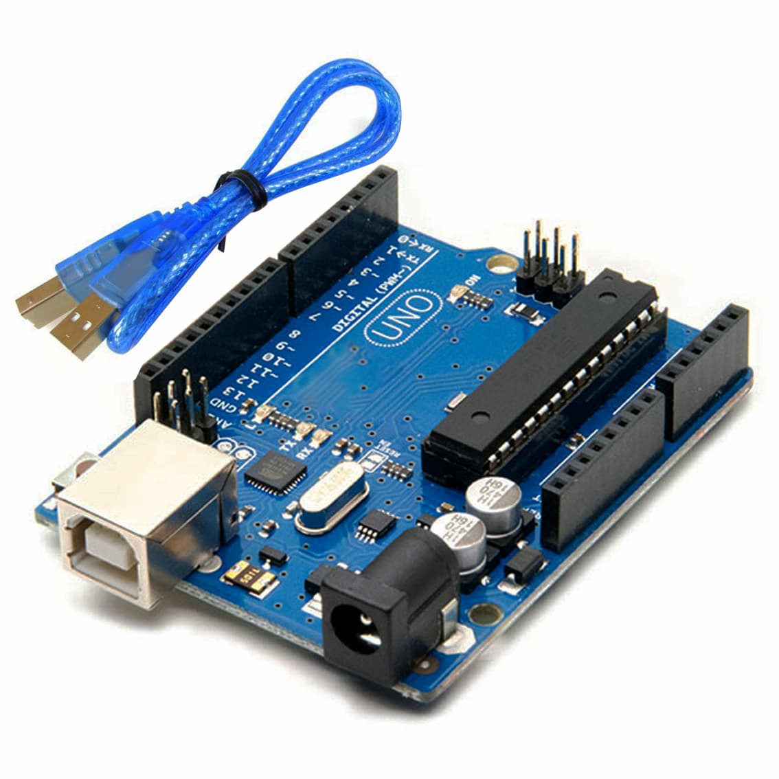
Figure 1: Arduino Uno
Photoresistor
A light-sensitive resistor that detects changes in ambient light levels. A photoresistor, sometimes referred to as an LDR (light-dependent resistor), changes resistance in response to incident light intensity. As the light intensity rises, the resistance falls. For the appropriate light detection sensitivity, it is crucial to select a photoresistor with a sufficient resistance range and reaction time.

Figure 2: Photoresistors
LEDs or Dimmable LED Bulb
Light-emitting diodes that provide the lighting output. Choose regular LEDs or dimmable LEDs depending on the desired functionality. When an electric current flows through semiconductor LEDs (Light Emitting Diodes), they release light. Consider the necessary forward voltage, forward current, and viewing angle while choosing LEDs. Select dimmable LEDs that have been created with dimming capabilities in mind. To change the brightness of these LEDs, pulse-width modulation (PWM) control is frequently needed.
Depending on the specific LEDs used, you may need current-limiting resistors to protect them from excessive current. The value of the resistor is determined based on the forward voltage and forward current specifications of the LEDs or dimmable LED bulbs being used. Use Ohm's law to calculate the appropriate resistor value (R = V/I) to ensure the LED operates within its safe operating range.
Jumper Wires
These wires are used to connect the various components. The Arduino, photoresistor, and LEDs are electrically connected via jumper wires. Depending on your unique needs, select jumper wires with the correct lengths and connections (e.g., male-to-male, male-to-female, female-to-female).
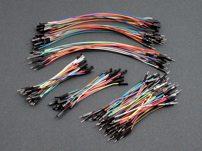
Figure 3: Jumper Cables
Breadboard or Perfboard
This is a prototyping board that allows you to easily connect and test electronic components. It has several rows of interconnected pins that allow you to create a circuit without soldering. Used to create the circuit connections on a prototyping platform.

Figure 4: Breadboard
Power Supply
A suitable power supply to power the Arduino and the LED. The power supply provides the necessary voltage and current to power the Arduino board and the LED lights. Ensure that the power supply voltage matches the operating voltage of the Arduino board (usually 5V or 3.3V) and consider the power requirements of the LEDs or dimmable LED bulbs. Select a power supply with the appropriate voltage, current capacity, and connector compatibility.
In case you choose to use a normal 120/240V bulb; you will need to add a relay to control the switching of the bulb. The bulb uses 120/240V thus a separate power supply or bulb holder is needed.
How to get started
To get started with this project, one needs to set up the hardware devices and make Arduino code for the Arduino microcontroller. The two parts depend on each other and any error in one will result in an error in the function of the system.
Below are some of the setups to get out of the way:
Setup
- Connect the photoresistor to the Arduino's analogue input pin. As an example, attach one leg of the photoresistor to the 5V pin and the other to the analogue pin A0. Create a voltage divider circuit by adding a resistor between the analogue pin and the ground.
- Connect the Arduino's digital output pins to the LED or dimmable LED bulbs. If required, use the proper current-limiting resistors.
- Connect the power supply's ground (GND) to the Arduino's ground (GND) pin.
- Provide the system with the necessary voltage and current by connecting the power supply to the Arduino's power jack or Vin pin.

Figure 5: Schematic of the Connection
- Open the Arduino IDE after setting up the Arduino board by using a USB connection to attach it to your computer.
Programming
For this project, two approaches can be used to achieve the desired lighting condition and LED functionalities. In case A, the bulbs controlled are normal bulbs/ LEDs, non-dimmable while in case B, we use dimmable LEDs, which offer a more controlled lighting function.
Here are the steps:
- Write the code in the Arduino IDE to read the analogue input from the photoresistor and control the LED(s) accordingly.
- In case A, the photoresistor senses the light level and once at a certain threshold, it triggers the relay to switch the bulb.
- In case B, the photoresistor is mapped to different brightness levels of the LEDs. Thus, we map the light level values from the photoresistor to the desired brightness range for the LED(s).
- Use the analogWrite() function to control the LED(s) brightness by supplying the appropriate PWM (Pulse Width Modulation) value.

Figure 6: Code for Case A

Figure 7: Code for Case B
Testing and Troubleshooting
- Upload the code to the Arduino board.
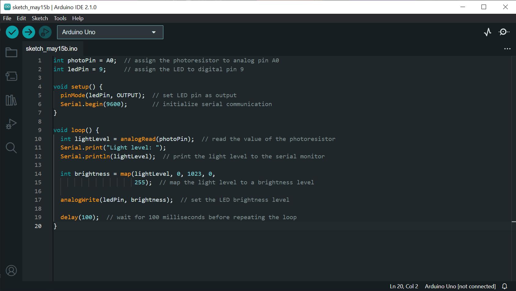
Figure 8: Code on the Arduino IDE ready for upload to the device
- Observe the behaviour of the LED(s) based on the ambient light level.
- Adjust the code or the circuit if necessary to achieve the desired functionality.

Figure 9: The electrical setup
- Troubleshoot any issues such as incorrect wiring, component failures, or incorrect code logic.
Once the code is set up and running, one can optimize the program to suit their need to offer more customizability. If this project is to be used as a long-term solution to an existing problem it is important to create an enclosure and a place to mount the setup. This ensures both safety and reliability for the system.
Importance of this Project
Energy Efficiency: By ensuring that lights are only turned on, when necessary, an automated light control system can assist to lower energy use. The device can help save power and save energy expenses by automatically turning lights on and off based on ambient light levels.
Convenience: Using an automated light control system eliminates the need for daily manual light switching. This is particularly useful in large houses or businesses where it could be challenging to remember to switch out the lights in every area.
Increased Comfort: A constant and comfortable lighting environment may be produced with the aid of an automated light control system. The system can assist by changing the brightness of the lights throughout the day.
Customization: The requirements and preferences of each user may be taken into account when designing an autonomous light control system. The system may be configured, for instance, to turn on specific lights at particular times or to change the brightness of the lights according to the time of day.
Integration with additional Smart Home Devices: Voice assistants, security systems, and thermostats are a few examples of additional smart home devices and apps that can be combined with an autonomous light management system. This might contribute to a smooth and practical experience with home automation.
Final Thoughts
The Automatic Light Control System with Arduino provides energy economy, practicality, and customization, in total. By automatically altering lights based on ambient light levels, it lowers energy usage while saving money. The method eliminates the need for manual switching and offers the ease of automated lighting management. By keeping constant illumination levels throughout a range of circumstances, it improves comfort. The flexibility to customize enables users to choose their schedules and brightness settings. Its possibilities within a smart home ecosystem are expanded by integration with other smart devices. Users may profit from energy savings, convenience, and a more intelligent lighting solution by putting this concept into practice. With Arduino, you can improve your lighting experience and bring greater comfort and efficiency to your home or place of business.