A transformer is a type of electrical equipment that is mainly used to change the AC voltage. A Flyback transformer (also known as a coil transformer or high frequency transformer) is a special type of electronic transformer that is designed to transmit electrical energy in a power supply circuit, converting the input voltage to a different output voltage in the process.
In devices such as televisions and computer monitors, a major application of flyback transformer is to generate the high voltage required to drive a cathode ray tube (CRT). At the same time, due to its working principle, flyback transformer also provides isolation to prevent current leakage between input and output.
The ordinary transformer realizes the instantaneous transfer of electrical energy between the primary and secondary coils, that is, the input current and the output current exist at the same time. The flyback transformer works in energy storage mode, that is, when the main coil is energized, it stores electrical energy. When the main coil is powered off, the stored energy is released to the load.
How Does a Flyback Transformer Works
Flyback transformer can be operated in continuous mode and disconnected mode:
Continuous mode: In continuous mode, voltage is applied to the main line winding of the excitation transformer, so that the regulating winding of the fly-back transformer generates flux, and the electric field energy of the high voltage main line is extracted, and then the power supply of the low voltage AC end is formed by the auxiliary wire winding of the excitation transformer, so as to achieve the function of voltage regulation.
Disconnected mode: In the disconnected mode, the circuit breaker of the excitation transformer is disconnected, and the magnetic flux in the flyback transformer will be disconnected, but the electric field energy in the main winding of the excitation transformer can still be extracted, and the voltage regulation function can also be achieved.
![]() Figure 1: principle of flyback transformer circuit
Figure 1: principle of flyback transformer circuit
The components of flyback transformer circuit include input capacitor, rectifier bridge and its accessory components, high-frequency transformer, output filter inductor and capacitor, power switch tube and its drive circuit, etc. These components are combined to build a complete flyback transformer circuit system.
The basic principle of flyback transformer circuit is to use high frequency switching technology to convert the input DC voltage into high frequency AC voltage, and then through the action of high frequency transformer, the required output voltage and current are finally obtained.
Specifically, when the power switch tube is on, the inductance L1 in the circuit stores electrical energy; When the power switch tube is closed, the inductance L1 in the circuit will release the stored electrical energy, generate a reverse current, and transfer the energy to the high-frequency transformer. Due to the rise and fall of the high-frequency transformer, the output will get the required voltage and current.
Design of flyback transformer
Flyback transformers are switching converters with relatively few components and are relatively easy to manufacture and design. Common components of flyback transformers are as follows: Flyback transformer, switch, rectifier, filter, drive switch, control device.
- flyback transformer
A transformer can transfer energy from the primary to the secondary. Flyback transformers, on the other hand, store energy in the primary magnetic field and transfer it to the secondary magnetic field after a certain amount of time.
The transformer consists of at least 2 inductors, called secondary coils and primary coils, wrapped in a coil rack with an iron core in the middle. The magnetic core determines the magnetic flux density, which is an important parameter for transferring electrical energy from one winding to another. Voltage phasing, points shown in primary and secondary windings.
- Switch
The function of the switch is to turn on and off the primary circuit, so that the transformer is magnetized and demagnetized. The switch is controlled by the PMW signal from the selected controller.
- Rectifier and filter
The rectifier recites the voltage in the secondary winding into pulsating direct current. Another function of the rectifier or diode is to cut off and connect the load from the secondary winding. The rectified voltage is then filtered by the capacitor to increase the DC level and made available for the intended application.
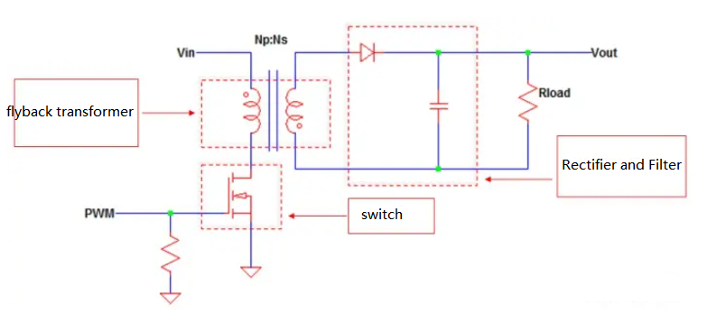
Figure 2: Flyback converter circuit schematic
There is no buffer circuit in the diagram above, but in fact, most of the time, flyback transformers need a buffer to counter voltage spikes on the switch or diode.
Advantage
1 Transformer has the advantages of excitation transformer, but also has the function of transformer, so the price is low, does not need redundant electronic equipment, can reduce the overall cost of the system, and has the protection function
2 Flyback transformer has low power consumption, reliable operation, wide adjustment range, no resonance, and can be used for strict adjustment tasks.
3 The use of flyback transformers can output a more stable voltage, so that the power grid voltage imbalance can be improved
4 The power factor of flyback transformer can also be controlled more accurately, and the filtering effect can be formed near a certain frequency, which greatly improves the quality of the power grid
5 Flyback transformer can be driven by closed-loop feedback, can be used to change the high-voltage side load to achieve a large range of accurate control, both to adjust the average output voltage, but also to stabilize the micro change of voltage, with self-regulation function.
Applications
1 Flyback transformers can be used to regulate and stabilize the output voltage, often used in solar photovoltaic, wind power generation systems and car battery chargers and other equipment.
Flyback transformers can be used to prevent the jitter of the output voltage and are often used in high-density power modules in data centers.
3 Flyback transformers can be used in substations for high-voltage distribution networks, transformer converter stations and line current regulation distribution
4 Flyback transformers can also be used in building electrical facilities for reliable high-power transmission and regulation of transformer output voltage.