What is MOSFET amplifier
An amplifier is an electronic device that enhances the amplitude of an input signal and is an essential part of audio sources such as record players or CD players, as well as other devices such as equalizers, preamplifiers, and speakers. MOSFET amplifiers are a subclass of amplifiers that use MOSFET technology to process digital signals with less power. Mosfets are used in amplification processes because they have high input impedance and low output impedance, allowing for high voltage gain. Today, MOSFET amplifiers are the design choice for 99% of the world's microchips.
MOSFET Amplifier Circuit
A. Detailed explanation of the circuit design
The simple circuit diagram of a MOSFET amplifier is shown in the figure below, in which the drain voltage (VD), drain current (ID), gate-source voltage (VGS), and the positions of the gate, source, and drain are indicated by the letters "G", "S", and "D".
In general, MOSFETs operate in the linear/ohmic, cut-off, and saturation regions. In these three regions, when MOSFETs are used as amplifiers, they should operate in the ohmic region, where the current flowing through the device increases as the applied voltage increases.
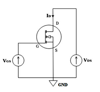 Figure:MOSFET amplifier circuit
Mosfets can be used as small signal linear amplifiers in many applications. Typically, in an amplifier circuit, the FET operates in the saturation region. Therefore, the flow of current in this region does not depend on the drain voltage (VD).
In simple terms, the current is the primary function of the grid voltage (VG). In these amplifiers, the operating point is usually within the saturation region.
In a MOSFET amplifier, a small change in the gate voltage will produce a large change in the drain current, as in a JFET. Therefore, the MOSFET increases the strength of the weak signal, so it can act as an amplifier.
B. Discussion on MOSFET amplifier and its theory
By connecting the source, drain, load resistance, and coupling capacitance to the above circuit, a complete MOSFET amplifier circuit can be designed, and the bias circuit of the MOSFET amplifier is as follows:
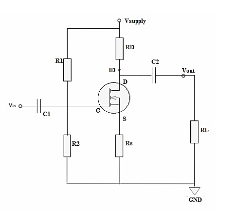
The bias circuit includes a voltage divider, whose main function is to perform a unidirectional bias on the transistor. Therefore, this is the most commonly used bias method in transistors. It uses two resistors to confirm that the voltage is separated and assigned to the MOSFET at the correct level. It is achieved by two R1 and R2 resistors in parallel.
C1 and C2 coupling capacitors in the circuit protect the biased DC voltage from the AC signal to be amplified. Finally, the output is supplied to the load formed by the RL resistor.
The formula for bias or grid voltage is as follows:
VG = Vsupply x (R2/R1 R2)
The values of R1 and R2 are usually large to enhance the input impedance of the amplifier and reduce ohmic power losses.
Input and output voltages (Vin and Vout)
For simplicity, it is necessary to consider that no load is in parallel with the drain branch. The input voltage (Vin) can be supplied through the gate (G) to the source (S) voltage, i.e., VGS. The voltage drop on the RS resistor can be given by RS×ID.
According to the transconductance (gm) definition, when a constant drain-source voltage is applied, the ratio of ID(drain current) to VGS(gate-source voltage) is:
(gm) = ID/VGS
Thus, ID = gm×VGS, and the input voltage (Vin) can be decomposed by VGS, as follows:
Vin = V GS x (1 gmRs)
The o/p voltage (Vout) is simply given by the voltage drop on the drain resistance (RD) :
Vout = – RD x ID = -gmVGS RD
In addition, the voltage gain (AV) is the ratio of the input voltage to the output voltage. After simplification, the equation will become:
Av = – RD/Rs=1/gm
In the above equation, the symbol "-" comes from the principle that the MOSFET amplifier inverts the o/p signal equivalent to the BJT CE amplifier. Thus, the phase shift is 180° or πrad.
Types of MOSFET Amplifiers
A. Breakdown of different types of MOSFET amplifiers
- Common Source (CS) MOSFET Amplifier: This is the most commonly used type of MOSFET amplifier. It provides high gain, high input impedance, and low output impedance. It's often used in general amplification and switching applications.
- Common Drain (CD) or Source Follower MOSFET Amplifier: This type of amplifier provides a voltage gain of approximately 1. It's mainly used for impedance matching and as a buffer stage due to its high input impedance and low output impedance.
- Common Gate (CG) MOSFET Amplifier: This type of amplifier is less commonly used and provides a high voltage gain. It has low input impedance and high output impedance. It's often used in high-frequency applications due to its inherently wide bandwidth.
- Class A, B, AB, and D Amplifiers: These are types of power amplifiers that use MOSFETs. Class A amplifiers are usually used in low-signal and low-noise applications. Class B and AB are typically used in audio amplification systems. Class D amplifiers are used in high-efficiency applications and are often found in consumer electronics like mobile phones and televisions.
B. Discussion on various MOSFET amplifier configurations
- Common Source Amplifier: This is the most common configuration. The input signal is applied at the gate and the output is taken from the drain. This configuration provides voltage amplification.
- Source Follower (Common Drain) Amplifier: In this configuration, the input is applied at the gate and the output is taken from the source. It provides unity voltage gain but high current gain. It's often used as a buffer due to its high input impedance and low output impedance.
- Common Gate Amplifier: The input is applied at the source and the output is taken from the drain in this configuration. It provides both voltage and power gain. This configuration is less common but can be used where a low input impedance and high output impedance are required.
- Push-Pull Amplifier: This configuration uses a pair of MOSFETs to amplify both halves (positive and negative) of the input signal. It's primarily used in power amplification stages.
- Differential Amplifier: This configuration uses two or more MOSFETs and amplifies the difference between two input signals. It's commonly used in operational amplifiers.
- Cascode Amplifier: This is a two-stage configuration that combines a common source amplifier with a common gate amplifier. It offers high gain and wide bandwidth.
Difference between BJT and MOSFET Amplifier
A. Comparative analysis of BJT and MOSFET amplifiers
- Operation: BJT is a current controlled device where the output characteristics are determined by the input current. On the other hand, MOSFET is a voltage controlled device where the output characteristics are determined by the input voltage.
- Power Consumption: BJTs consume more power compared to MOSFETs due to the need for input current. MOSFETs have high input impedance and thus consume less power, making them more energy efficient.
- Gain: BJTs usually have higher gain compared to MOSFETs. This makes BJTs more suitable for applications where high gain is required.
- Frequency Response: MOSFETs generally have better frequency response than BJTs, making them a more suitable choice for high frequency applications.
- Noise: BJTs are more prone to noise compared to MOSFETs. This is due to the fact that BJTs have a higher degree of thermal noise due to the need for biasing current.
- Complexity: BJTs are generally easier to use and less complex than MOSFETs. This is due to the simpler structure and operation of BJTs.
- Durability: MOSFETs are usually more durable and have a longer lifespan compared to BJTs.
B. Explanation of use cases
BJT Amplifier Use Cases:
- Audio Amplification: BJTs are commonly used in audio amplifiers because of their high gain characteristics.
- Signal Amplification: BJT amplifiers are often used in signal amplification circuits due to their ability to amplify weak signals.
- Oscillator Circuits: BJTs are used in oscillator circuits due to their ability to handle rapidly changing signals.
MOSFET Amplifier Use Cases:
- Power Amplification: MOSFETs are often preferred for power amplification due to their high input impedance and low output impedance, which leads to high power efficiency.
- High-Frequency Applications: MOSFET amplifiers can handle high-frequency signals better than BJT amplifiers, making them suitable for applications like RF amplifiers.
- Switching Applications: MOSFETs are commonly used in switching applications due to their fast switching speed and high power efficiency.
In summary, the choice between BJT and MOSFET amplifiers depends on the specific needs of the application. BJTs are typically preferred for their high gain and simplicity, making them ideal for audio and signal amplification. On the other hand, MOSFETs are preferred for their power efficiency and high-frequency handling, which makes them ideal for power amplification and switching applications.
Advantages of MOSFET Amplifiers
- High Input Impedance: MOSFETs have very high input impedance, typically in the mega-ohm range. This means they draw very little input current, making them highly efficient.
- Low Output Impedance: They have low output impedance, which makes them suitable for driving low impedance loads, such as speakers.
- High Speed: MOSFETs can switch on and off very quickly, allowing them to handle high-frequency signals effectively. This makes them ideal for high-frequency applications such as RF amplifiers.
- Power Efficiency: Due to their high input impedance and low output impedance, MOSFET amplifiers are very power efficient.
- Thermal Stability: MOSFETs are generally more thermally stable than other types of transistors, such as BJTs, which makes them more reliable in high temperature applications.
- Simplicity: MOSFET amplifiers are voltage-driven, which simplifies the design of amplifier circuits.
- Durability: MOSFETs are less susceptible to damage from overloads or short circuits, making them relatively durable.