Diodes are the most commonly and widely used electrical components, whether in AC or DC circuits. These components can be used for an array of applications as well as to achieve different circuits, with the most common being providing directional flow, other applications involve; Rectifying a voltage: turning AC into DC, controlling and isolating the size of a signal, mixing (multiplexing) signals and others.
Essentially, in any circuit that you handle, there is a very high chance that there is a diode. For engineers, technicians, electricians and anyone dealing with electrical circuits it is important to understand how diodes work and how to test them in case you suspect fault.
These little but crucial components are tricky and can be very sensitive, hence need to be thoroughly tested. However, diodes are easy to test with a simple multimeter.
WHAT IS A DIODE?
A diode is a semiconductor component, with two terminals that is used to control the flow of current in one direction. Essentially it acts as a one-way current switch, allowing the flow in one direction and restricting the flow in the opposite direction. As two-terminal components, diodes have polarity with an anode (positive) and cathode (negative).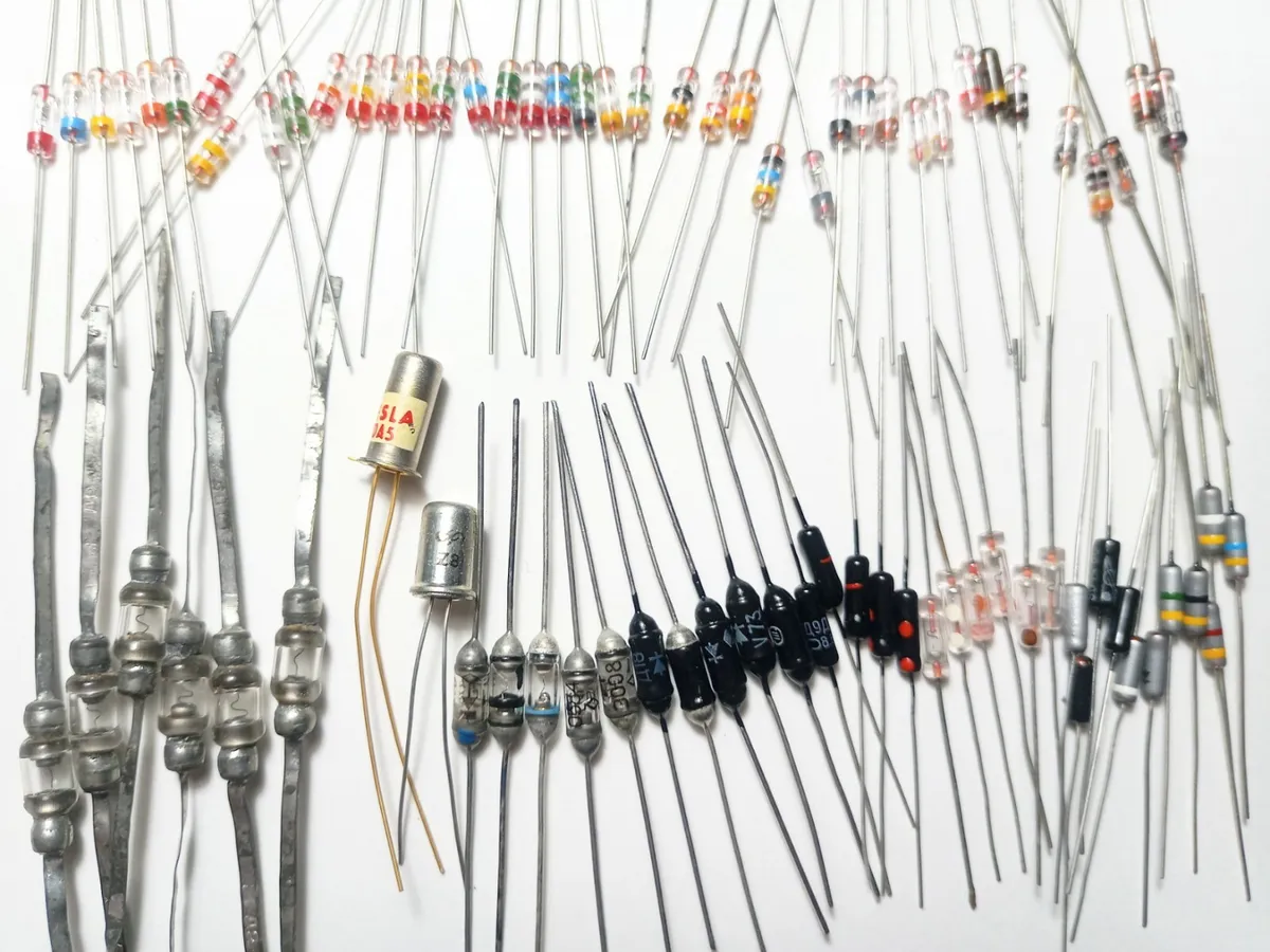
Figure 1: Variety of diodes
A diode allows current to flow when the anode is connected to the positive terminal of the power supply. In this connection, a diode allows current to flow, this is called forward bias. When the terminals are interchanged a diode acts as an insulator and no current flows, reverse-bias mode.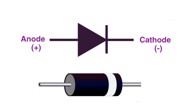
Figure 2: Sample Diode and Symbol
Ideally, diodes have zero (low) resistance in one direction and an infinite (very high) resistance in the other direction.
HOW TO TEST A DIODE
To ensure correct functionality, it is important to test a diode. The easiest way to test a diode is using a digital multimeter. It is important to use a digital multimeter with diode mode, in this mode the multimeter produces a small voltage between the leads, enough for silicon diodes.
However, for a thorough assessment of a diode's characteristics, such as its voltage and current ratings, consult the diode's datasheet or employ specialized diode testing equipment.
Required Tools
Digital Multimeter (DMM): This is an essential electrical testing tool that allows you to measure various electrical parameters, including voltage, current, and resistance.
Make sure your DMM has a diode testing mode.
Method of Testing a Diode
When using a digital multimeter there are two methods of testing the diode:
- Diode Mode Test: This mode is made to specifically test diodes. It is the best option for testing diodes.
- Testing the resistance: Typically using diode mode is preferred. However, if the diode is not equipped testing for resistance can be used.
In most cases when testing a diode, especially using resistance mode it is necessary to remove at least one end of the diode from the circuit. This might produce false results. It should be used as a method to verify the diode test results.
Diode Mode Test
A diode is best examined by measuring the voltage drop across it when it is forward-biased. A forward-biased diode functions as a closed switch, allowing current to flow. When connected to a diode, the multimeter produces a small voltage drop across the lead. This indicates a forward bias mode.
Procedure.
- Make sure the circuit is off and no voltage exists within the circuit i.e., from connected capacitors.
- Check that your digital multimeter is operating properly by turning it on.
- Use your multimeter diode testing mode. This mode is often represented by a voltage drop sign or a diode symbol (→|). If you're not sure how to switch your multimeter to diode mode, consult the user guide.
- For correct findings, make sure the black probe is entered into the common (COM) jack and the red probe is plugged into the positive (often labelled as VΩmA) jack.
- Connect the diode to the test leads. Note the measurement of the readings.
- Reverse the test leads. Note the measurement observed.
Expected Results
In the forward-bias direction (red probe on the anode, black probe on the cathode), your multimeter should display a voltage drop. This decrease commonly occurs between 0.6 and 0.7 volts in the case of common silicon diodes. A voltage drop of 0.2 to 0.3 volts is possible for Schottky diodes.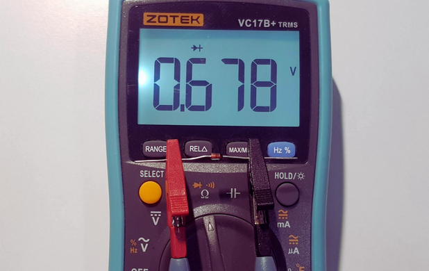
Figure 3: Diode Mode Forward Bias
In the reverse-bias direction (red probe on the cathode, black probe on the anode), the multimeter should show "OL" (indicating an open circuit) or display a very high resistance value. This shows that the diode is obstructing the reverse current flow.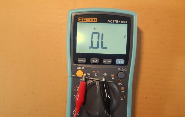
Figure 4: Reverse Bias
A defective (opened) diode prevents current from moving in either direction. When the diode is opened, an OL signal will appear on a multimeter in both directions.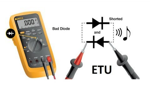
Figure 5: Defective Diode
On the other hand, a voltage drop indicates a shorted diode. The voltage drop is the same (about 0.4 V) in both directions.
Resistance Mode Test
As mentioned earlier, this mode is majorly used as a test to verify results from the diode test mode. However, if there is no diode mode it can be used.
Procedure:
- Make sure the circuit is off and no voltage exists within the circuit i.e., from connected capacitors.
- Check that your digital multimeter is operating properly by turning it on.
- Set the dial to the Resistance position (Ω). It might share a dial position with another feature.
- Connect the test leads to the diode after it has been removed from the circuit. Note the measurement.
- Place the red (positive) probe on the anode side of the diode.
- Position the black (negative) probe on the cathode side of the diode.
- Turn the test leads around. Note the measurement.
- When testing diodes in the resistance mode, compare the values with those of a known-good diode for the best results.
Expected Results
In forward-biased, the resistance of a good diode should range from 1000 Ω to 10 MΩ. A relatively low resistance value indicates that the diode is conducting in the forward direction, which is expected behaviour.
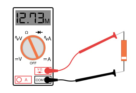
Figure 6: Resistance Mode forward bias
An OL signal is shown on a multimeter by the reverse-biased resistance of a good diode. The OL reading indicates a high resistance value. In reverse bias the is blocking the current as it should. If the readings are the same in both directions, the diode is defective.
CONCLUSION
In conclusion, depending on your preferences and the capabilities of your multimeter, you can test a diode using a digital multimeter in either the resistance mode or the diode testing mode. Diode testing mode is a rapid and accurate approach to examining the functionality of a diode since it delivers a particular voltage drop reading in the forward bias direction and an open circuit or high resistance in the reverse bias direction.
These methods provide the fundamental tests for diodes. These are complemented by an assessment of the diode’s characteristics, such as voltage and current ratings. However, these may need the use of specialized equipment.