What is Clamping Diode
Clamping diodes are a common electronic component, also known as protection diodes or baropendulum diodes. It has a special voltage response characteristic, which plays a role in limiting and protecting the signal in the circuit. Clamp diodes are usually made of materials such as germanium, silicon, or silicon carbide, and have the advantages of high speed response and low leakage current. Clamp diode is a kind of diode with special voltage response characteristics. It has a low resistance during forward conduction, which can limit the signal in the circuit to a safe range. When the input voltage exceeds a certain critical value, the clamp diode automatically starts to switch on, maintaining the voltage near this critical value. This critical value is called the clamp voltage and can also be understood as the controlled braking voltage of the clamp diode.
Working Principle
When the negative electrode of the diode is grounded, when the potential of the positive extreme circuit is higher than that of the ground, the diode will pull its potential down, that is, the positive extreme circuit is clamped to zero potential or below zero potential (ignoring the tube pressure drop).
When the positive electrode of the diode is grounded, the potential of the negative extreme circuit is higher than the ground, the diode will be cut off, and its potential will not be affected by any diode.
Functions
Voltage limitation: Clamp diodes can limit the voltage in the circuit to a specific range, preventing the component from being damaged by excessive voltage.
Protection element: When the voltage in the circuit exceeds the rated voltage of the clamp diode, the clamp diode will switch on, directing the excess voltage to the ground or elsewhere, thereby protecting other components in the circuit from damage.
Waveform shaping: In the signal processing circuit, the clamp diode can also be used to shape the signal waveform to ensure that the output waveform meets the requirements.
Voltage regulation: Clamping diodes can also be used in voltage regulation circuits to help maintain a stable voltage in the circuit.
In general, clamping diodes play an important role in circuit design, such as limiting voltage, protecting components and waveform shaping, and play an important role in circuit performance and stability.
Clamp diode circuit
According to the circuit structure, the clamp diode has two circuit modes, one is a simple type and one is a bias type.
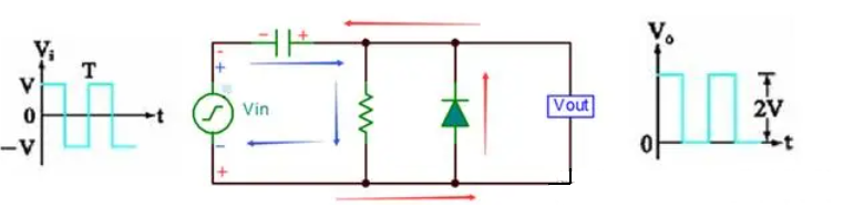
Simple positive clamp circuit
Circuit principle: When the input Vin is negative half a week (Vin is negative and positive), the diode is switched on, the current is shown as the red arrow, the capacitor is charged to V (left negative and right positive), Vout=0V; When the input Vin is in positive half cycle (Vin is positive and negative on the bottom), the diode is cut off, the current is shown as the blue arrow, Vout voltage is equal to the capacitor voltage plus positive half cycle voltage, so Vout=2V;
Simple positive clamp circuit
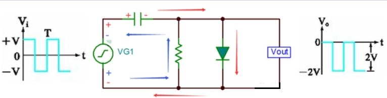
Simple negative clamp circuit
Circuit principle: Input Vin in positive half week (Vin is positive and negative), diode conduction, current as shown by the red arrow, capacitor at both ends of the differential pressure charge to V (left positive and right negative), Vout=0V;
When the input Vin is negative half cycle (Vin is negative and positive on the bottom), the diode is cut off, the current is shown as the blue arrow, and the Vout voltage is equal to negative (capacitor voltage negative half cycle voltage), that is, Vout=-2V;
Simple negative clamp circuit
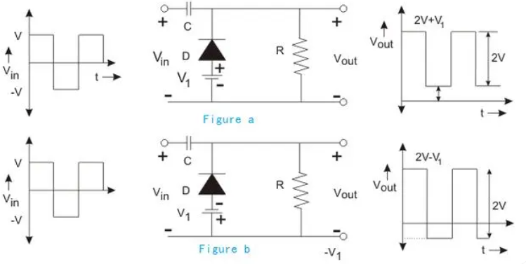
Bias type positive clamp circuit
A bias clamp circuit is similar to a limiter circuit in that a bias voltage is added to the circuit to raise or lower the clamp value.
Figure a shows the forward bias type. When the bias applied is consistent with the diode conduction direction, the waveform is upward, that is, the clamp value will increase V1.
Figure b shows the reverse bias type. When the bias applied is opposite to the diode conduction direction, the waveform is downward, that is, the clamp value will decrease V1.
Bias type positive clamp circuit
Bias type negative clamp circuit
A biased negative clamp is similar to a biased positive clamp in that a bias voltage is added to the circuit to raise or lower the clamp value.
Figure C shows the reverse bias type. When the bias applied is opposite to the diode conduction direction, the waveform is upward, that is, the clamp value will increase V1.
Figure D shows the forward bias type. When the bias applied is the same as the diode conduction direction, the waveform is downward, that is, the clamp value will decrease V1.
ALSO READ: Exploring the Zener Diode| Definition, Uses & Fuctions
Clamp diode circuit applications
1 Signal limiter: In the communication system, the amplitude of the signal may be affected by various factors and change. In order to ensure that the signal is within a certain range and does not exceed the processing capacity of the receiving circuit, a clamp diode circuit can be used as a signal limiter. By adjusting the parameters of the resistor and diode, the input signal can be limited to a specific amplitude range.
2 Power regulator: In electronic equipment, a stable power supply voltage is very important. The diode clamp circuit can be used as a power regulator to limit fluctuations in the input power supply to a small range to ensure a stable operating voltage. This is very important for some equipment with high voltage requirements, such as precision measuring instruments and computer systems.
3 Temperature compensation: the on-voltage of the diode is negatively correlated with temperature. Using this property, diode avant-garde circuits can be used for temperature compensation. By connecting a diode to a thermistor, when the temperature changes, the resistance value of the thermistor will change accordingly, so that the on-voltage of the diode remains stable.
4 Waveform correction: In analog circuits, the waveform of the input signal may be distorted or disturbed by noise. By using the clamp diode circuit, the waveform of the signal can be corrected, unnecessary noise can be removed, and the signal can be limited to a more stable range.
5 Voltage detector: The clamp diode circuit can be used as a voltage detector to detect whether the input voltage exceeds or falls below a certain set value. When the input voltage exceeds the set value, the diode will be switched on, triggering the action or alarm of the subsequent circuit.
FAQS
1 Q: What is the difference between a Zener diode and a clamping diode?
By providing clamp diodes in a comparator circuit, the diodes ensure that the output voltage remains within safe operating limits, protecting the comparator and other components in the circuit from overvoltage conditions. Clamp diodes help stabilize the output voltage and maintain the integrity of the comparator's operation, making the circuit more reliable and robust.
3 Q: What does a clamping diode protect the circuit from?
A: A clamping diode protects the circuit from overvoltage conditions. When a clamping diode is included in a circuit, it helps limit the voltage across a specific component or portion of the circuit to a safe level. This protection is crucial in preventing damage to sensitive components or integrated circuits that may be unable to withstand high voltage levels.
By effectively clamping the voltage and diverting excess voltage away from critical components, the clamping diode safeguards the circuit from potential voltage spikes, transient voltage surges, or other forms of overvoltage events that could otherwise lead to component failure or circuit damage.